Left Toolbar > ![]() 3D Nodes >
3D Nodes > ![]()
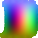
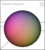
The Mesh Position node renders the position of the pixel in the mesh relative to a bounding box. The X coordinate is rendered in the red channel, the Y coordinate is rendered in the green channel and the Z coordinate is rendered in the blue channel. The bounding box can be defined by the model, by the whole scene, or by a point and size defined in the attributes.
models
 Img
Img
output
 Img
Img
 Img
Img
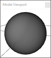
Load one of more model in the Scene Window.
On the left toolbar choose 3D Nodes > Mesh Position. ![]() >
> ![]()
Drag the Mesh Position icon into the Node Graph.

Connect the output socket into the Img socket in the Mesh Position node.
Adjust the attributes of the Mesh Position node to modify it.
Img
An RGB image.
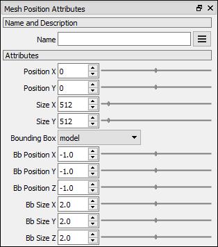
Position X Position X of the output image.
Position Y Position Y of the output image.
Size X Size X of the output image.
Size Y Size Y of the output image.
Bounding Box The bounding box that will be used to render the relative position. model: Each pixel is rendered relative to the bounding box of its own model. scene: Each pixel is rendered relative to the bounding box of the entire scene. Note. The model transform values affect the image output. scene: Each pixel is rendered relative to a bounding box defined by the position and size points. Note. The model transform values affect the image output.
Bb Position X Defines the position x coordinate of the custom bounding box.
Bb Position Y Defines the position y coordinate of the custom bounding box.
Bb Position Z Defines the position z coordinate of the custom bounding box.
Bb Size X Defines the size x of the custom bounding box.
Bb Size Y Defines the size y of the custom bounding box.
Bb Size Z Defines the size z of the custom bounding box.