Pixaflux
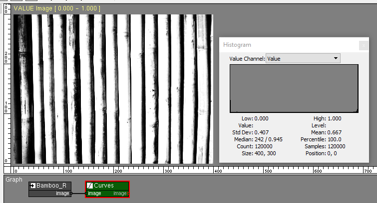
Working with VALUE images
VALUE images have one channel, and the values in this channel can have any 32 bit real value.
Download the tutorial files.
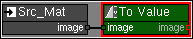
To Value Node
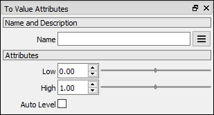
The To Value node converts any image to a VALUE image.
RGBA image:
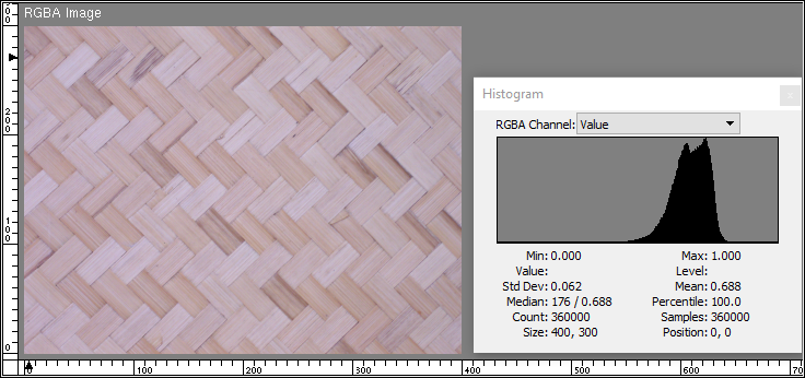
Converting to VALUE.
To convert and RGBA or NORMAL image to VALUE use the To Value node.
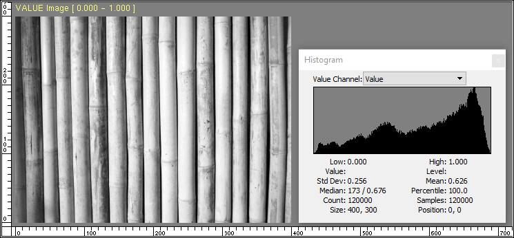
The image is converted by default to the 0.0 to 1.0 range.
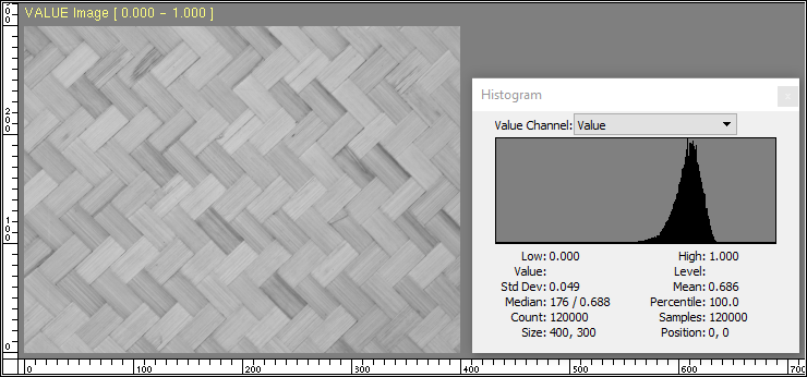
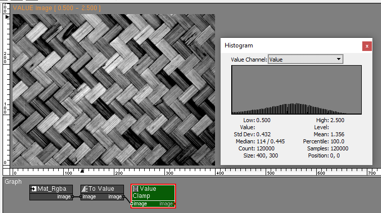
Notice in the histogram how most of the values of the image are in the 0.5 to 0.8 range.
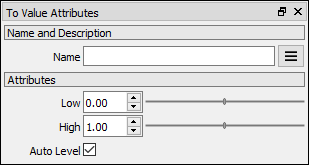
The Auto Level attribute finds the lowest and highest values in the image and interpolates the values in this range and maps them between Low and High, covering the whole range.

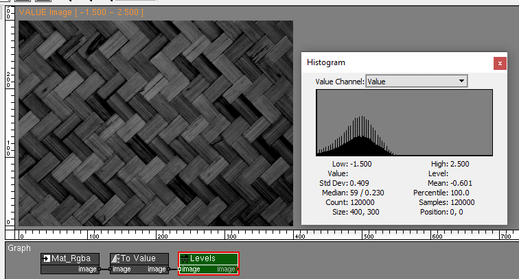
The user can define the output range of VALUE images generated by the To Value node by setting Low and High attributes.
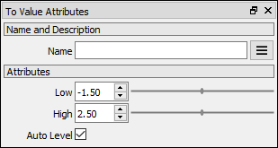
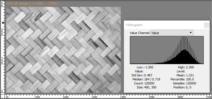
Notice how this image in the -1.5 to 2.5 range looks the same to the one in the 0.0 to 1.0 range. The image viewport title and the histogram tell us that this VALUE image Min and Max values are -1.5 and 2.5.
Displaying images in a computer screen is limited to intensities between 0.0 and 1.0, and for this reason PixaFlux converts both images to a 0.0 to 1.0 range before displaying it in the screen. This is why the image in the 0.0 to 1.0 range looks the same as the image in the -1.5 to 2.5 range.
Reading VALUE images from storage
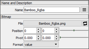
The Image Reader node Format attribute can convert the image in disk to a VALUE image. The image is created in the 0.0 to 1.0 range without auto leveling it.
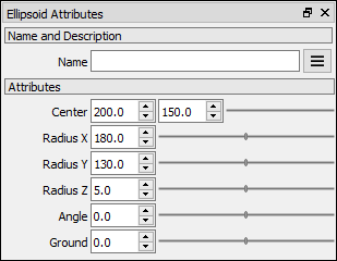
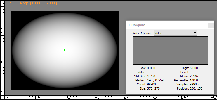
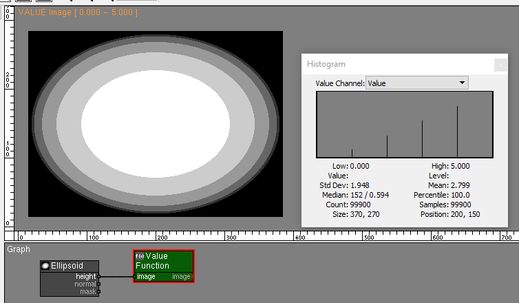
VALUE shapes
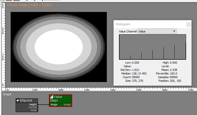
The wave, ellipsoid and cylinder nodes generate VALUE images with the height map of these shapes.
Operations with VALUE images
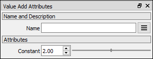
PixaFlux support various mathematical operations of images using the Value nodes. These nodes apply the mathematical operation to pixels at the same world position. Some of these operations work with only two inputs, some work with multiple inputs. These nodes also have a constant attribute that is applied to the whole image.
AutoLevel
Many nodes that work with VALUE images apply an AutoLevel operation to the output image. If the low and high values of the range fall between 0.0 to 1.0, the AutoLevel operation sets low and high to 0.0 and 1.0 to keep the images in a monochromatic range.
Operations with multiple images and constant
Operations like addition, multiplication, minimum and maximum take as input multiple images and a numeric constant attribute.
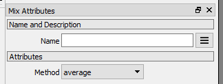
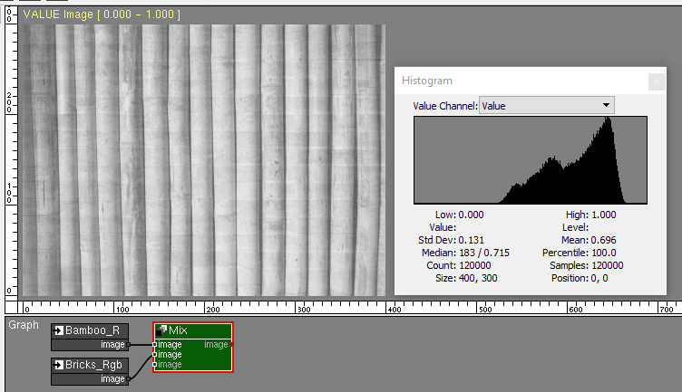
Addition
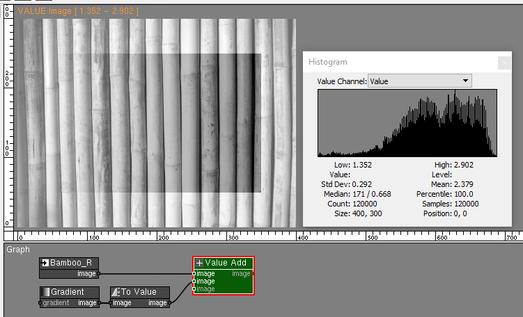
Adding the Mat and Bamboo images generates an image with an auto leveled range.
The addition node also adds the constant to all pixels of the image.

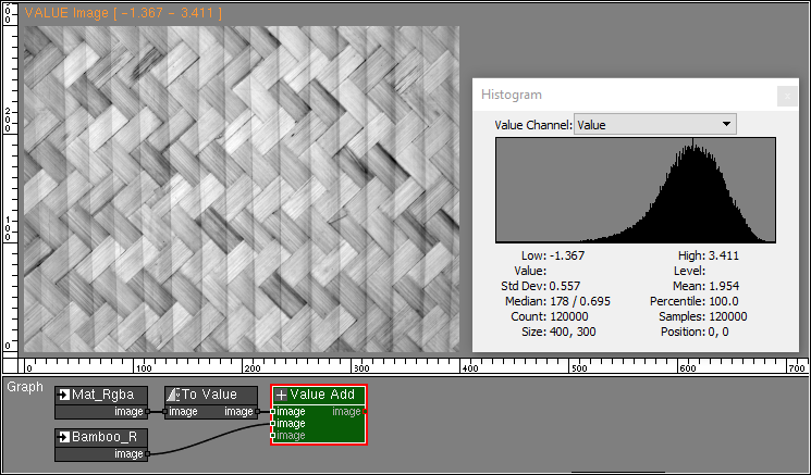
The Value Add node supports multiple images. Adding the ellipsoid.
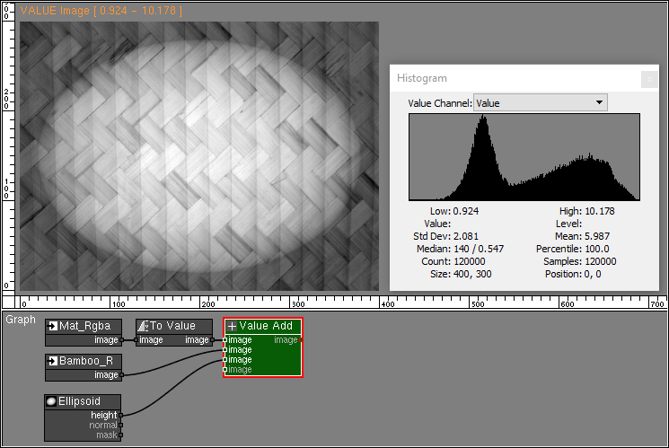
When images of different sizes or positions are used in VALUE operations, the value at the lower left corner of the images is used in the out of bounds regions.
In this addition operation the ellipsoid image starts at [15, 15] and ends at [384, 284]. Outside this area the low value of 0.0 is used in the addition operation.
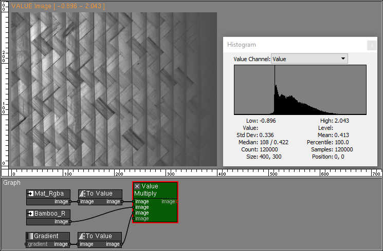
Multiplication
The Value Multiply node multiplies the values of all images and the constant.
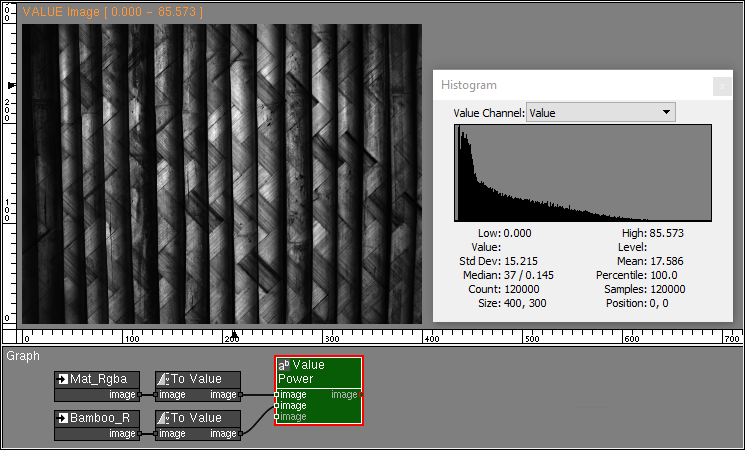
Power
Minimum and Maximum
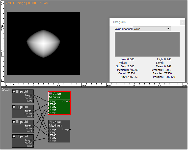
The Value Minimum node finds the minimum value between all pixels and the constant attribute.
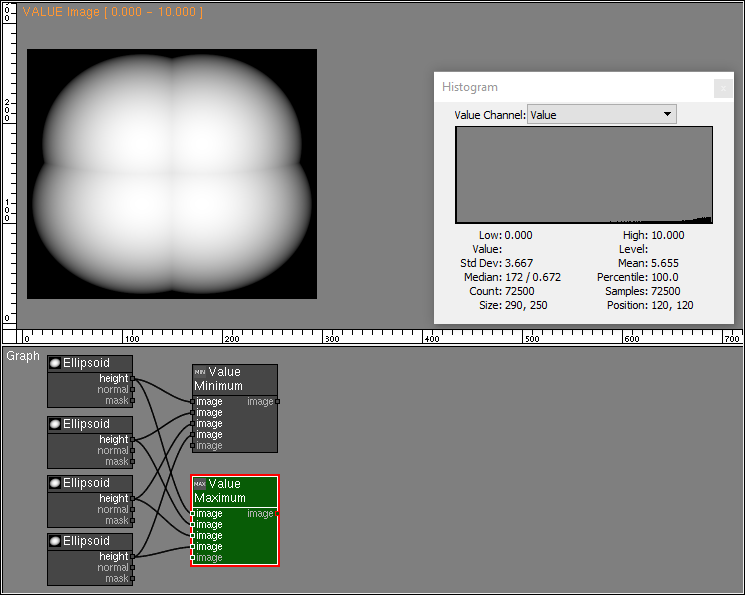
The Value Maximum node finds the maximum value between all pixels and the constant attribute.
Operations with two images
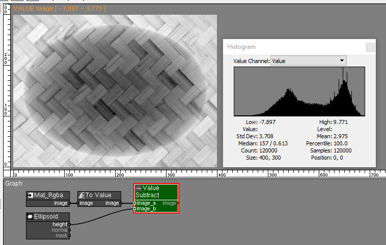
Subtraction
Division
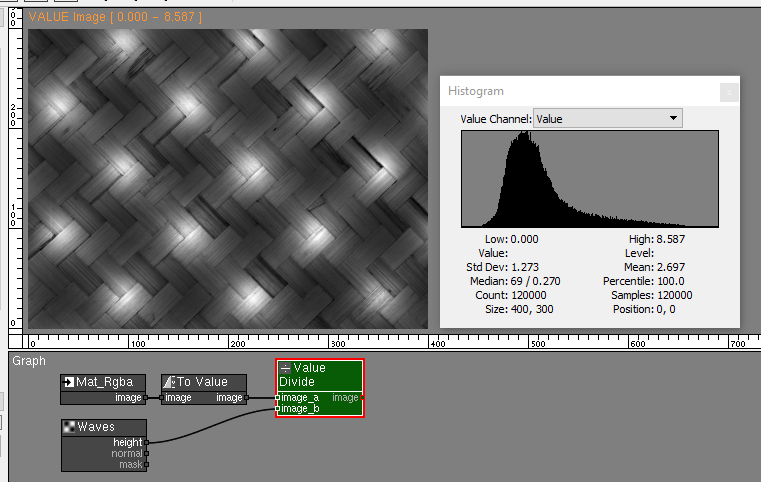
Be careful with division by 0.0 when using the Value Divide node as it might generate images with invalid pixel values.
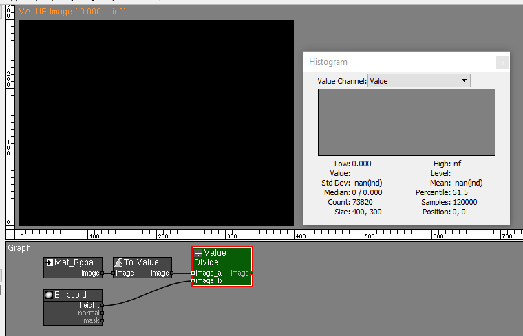
Notice in the histogram the inf high range value, and the nan standard deviation and mean values. These are signs that the image has invalid values.
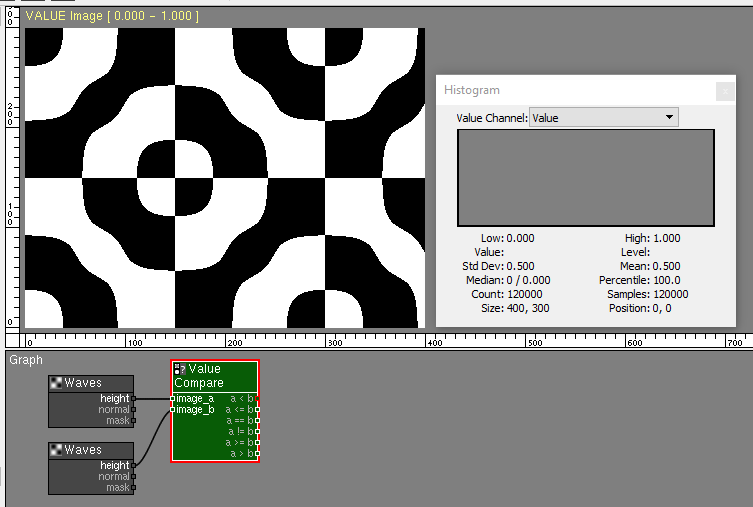
Compare
The Value Compare node compares the value at each pixel of the input images and generates the output images based on a conditional, where 0.0 is false, and 1.0 is true.
Operations on one image
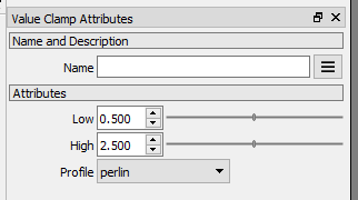
Clamp
The Value Clamp node restricts the values of the image to a new range. Additionally it provides a profile curve that remaps the image tonality.
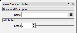
Steps
The Value Steps node reduces the gradation of the image to a selected number of tones.
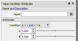
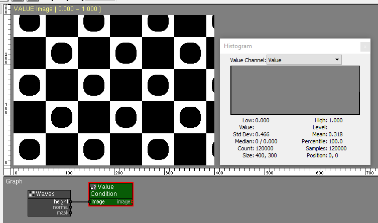
Condition
The Value Condition node executes the conditional statement at each pixel of the input image. If true, the pixel value is set to 1.0. If false, the pixel value is set to 0.0.
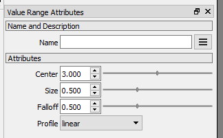
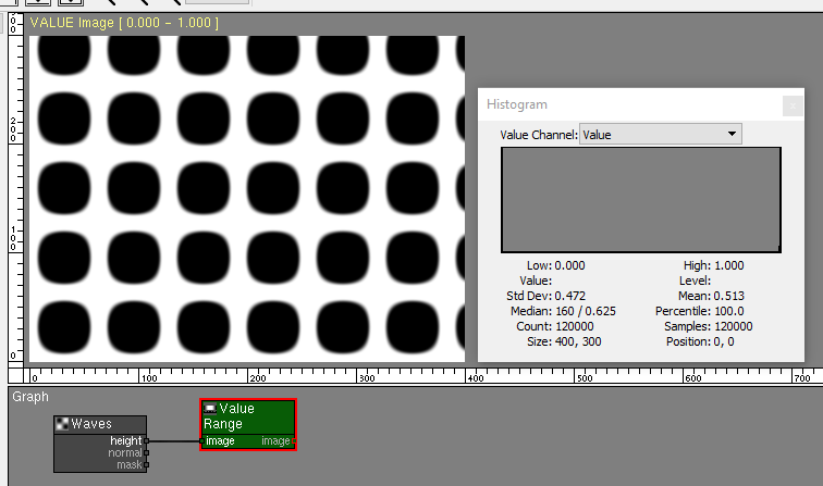
Range
The Value Range node returns a smooth region around a value.
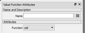
Function
The Value Function node performs a mathematical function on each pixel of the image.
Other nodes that support VALUE images
Many other PixaFlux nodes support operations on VALUE images.
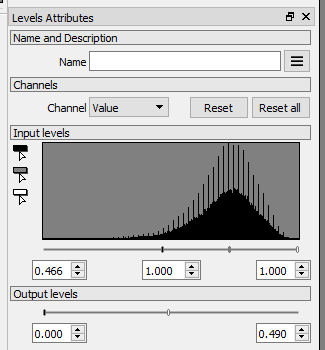
Levels
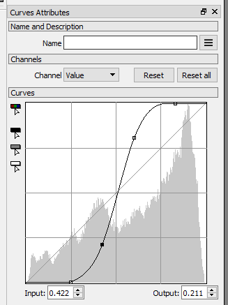
Curves